The button that pressed itself (not)
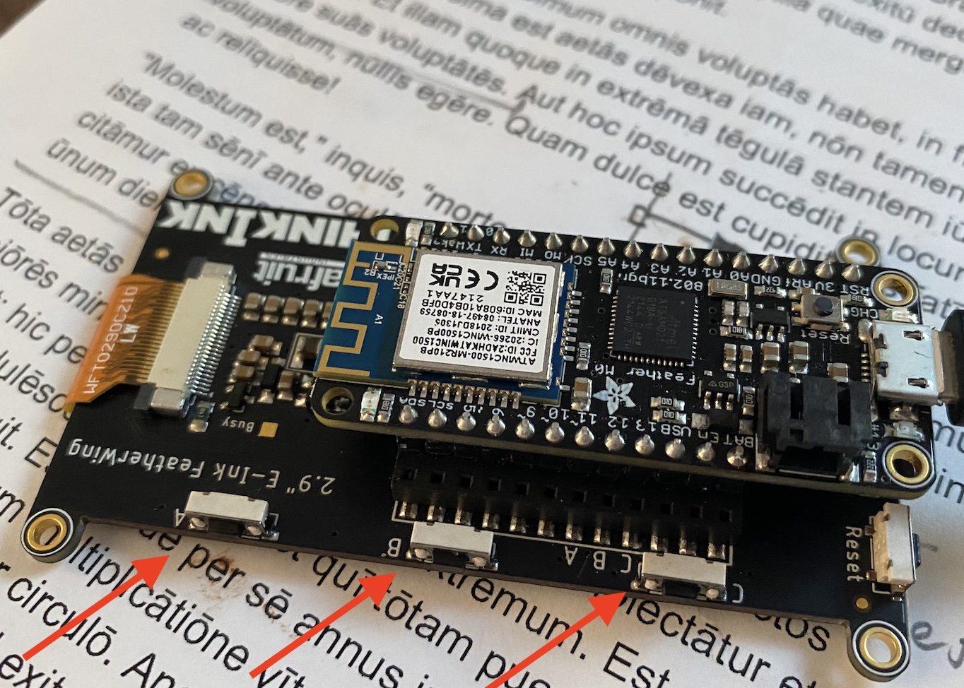
I recently bought a new (larger) e-Ink display from Adafruit: 2.9” ThinkInk FeatherWing. It comes with the usual SD card, memory and differently from the previous versions with 3 convenient buttons.
I thought about putting the buttons to good use, so decided to assign each one for a different function:
- KEY_A -> get a random quote from my back-end and display it.
- KEY_B -> scroll the quote in case it was too long to display and needed multiple pages.
- KEY_C -> synch the internal clock with NTP.
The display pin-out is set in a way that KEY_A, KEY_B and KEY_C are wired directly to GPIO pins 11, 12 and 13 on the main board. Convenient. When you press the button, you are grounding the pin; and therefore the reading would be LOW (0 V). Releasing the button leaves the pin “open” which means we need pull-ups resistor.
Thankfully, the INPUT_PULLUP option for GPIO’s with Arduino is precisely for this. Arduino’s have internal resistors and it is easily done with the pinMode function:
pinMode(KEY_A, INPUT_PULLUP);
pinMode(KEY_B, INPUT_PULLUP);
pinMode(KEY_C, INPUT_PULLUP);
Because the input is configured as a
pull up, when then button is released, you readHIGH. So logic is “reversed”.
The main loop of my program now looks something like this:
  Keys keys;
  ...

  //Button triggered actions
  if(keys.isA()){
    actions.getRandomQuoteAction();
  }

  if(keys.isB()){
    actions.scrollQuoteAction();
  }

  if(keys.isC()){
    actions.synchClockAction();
  }
Keys is a simple class that encapsulates the GPIO configuration. I also added some very basic de-bouncing capabilities to avoid multiple triggers (de-bouncing).
The Mysterious key “press”
Everything worked as expected, mostly… I had to adjust a bouncing delay to prevent one press to be read as twice. But the mystery was with KEY_C, which every once in a while triggered on it’s own.
I reviewed the configuration, the wiring…I thought about soldering an external pull-up resistor. I was about to butcher the entire board, when I figured I’d read the board documentation, and there it was:
...
#11 - GPIO #11
#12 - GPIO #12
#13 - GPIO #13 and is connected to the red LED next to the USB jack
...
Pin 13 (connected to KEY_C) is ALSO connected to the built-in LED. Months ago I added a timer to toggle the LED every few seconds. Every time I turned the LED off, I was grounding the pin, essentially, mimicking what the button does. Mystery solved.
I thought (wrongly) that by configuring a GPIO as INPUT all outputs would be ignored. But it turns out they aren’t. And now a bug is a feature. All buttons have software equivalents.